
Upgrade your CNC machine with this high-precision Advanced CNC Motion Control Mainboard, designed for makers, hobbyists, and light-industrial projects. This controller supports multiple stepper motors, limit switches, servo motors, and spindle control, giving you a complete automation core in one compact board.
The board features clearly labeled connection ports for X/Y/Z/A axes, helping ensure stable and accurate motion control. It also includes input support for end-stop switches, giving your machine better safety and cutting precision. With integrated USB connectivity, the board easily links with your computer for smooth G-code operation and real-time command handling.
Whether you’re building a CNC router, laser engraver, robotics system, or a DIY automation project, this controller delivers reliable performance with simplified wiring and strong compatibility.
Key Features
Ideal for CNC routers, engravers, PCB machines, and DIY robotics
Supports 4-axis stepper motor control
Compatible with servo motors and spindle modules
Includes multiple limit switch inputs for safety and accuracy
USB & power supply ports for easy connection
Stable circuit layout for smooth, low-noise motion
1. Decide what CNC you want
Pick one first:
- Small CNC router (wood, plastic, PCB)
- Laser engraver
- Pen plotter / foam cutter (easiest)
For your first build, I’d suggest:
Small 3-axis CNC router or laser engraver, work area around 30×18 cm (3018 size).
You can use almost the same electronics for both.
2. Main parts you need
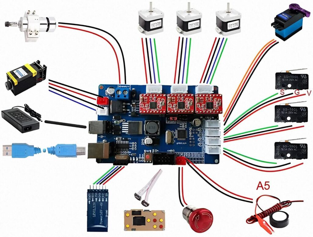
From the image, this is the basic setup:
🔌 Electronics
- CNC controller board (like in the picture)
- Often GRBL-based (Arduino + drivers in one board)
- Stepper drivers (the 4 red modules on top) – A4988 / DRV8825
- Stepper motors – usually NEMA 17 or NEMA 23 (X, Y, Z)
- Power supply – e.g. 24V / 5–10A
- Limit switches – little black switches on right (S/G/V = Signal / Ground / VCC)
- Spindle or laser module
- Optional: emergency stop button, fan, Bluetooth/WiFi module
🛠 Mechanical frame
- Aluminum profiles (2040 / 2020) or old printer/3D-printer frame
- Linear rails or smooth rods + bearings
- Lead screws + couplers (or timing belts + pulleys)
- Spindle mount / laser mount
- Bed / table (MDF, plywood, aluminum plate, etc.)
3. Very simple build plan
Step 1 – Start with the electronics on the table
Before you build the frame, make the electronics work alone:
- Mount stepper driver modules on the board.
- Connect one stepper motor (for example to X axis).
- Connect the power supply to the board (double-check polarity!).
- Connect board to PC via USB.
- Install a sender program like Candle / UGS / LaserGRBL.
- Send small moves (like
X10,X-10) and see the motor spin.
When one motor moves correctly, it becomes much easier.
⚠️ Safety:
- Never touch live wires.
- Always disconnect power when wiring.
- Drivers can burn if you plug/unplug motors with power on.
Step 2 – Build the frame (mechanical)
For a basic 3018-style router:
- Make a rectangle base from 2040/2020 aluminum and mount the Y rails on it.
- Put a moving bed on linear rails or wheels and drive it with a lead screw or belt (Y axis).
- Build a gantry (bridge) that moves left-right (X axis).
- Add Z axis on the gantry for spindle/laser up and down.
If this sounds too hard, another path:
Buy a cheap 3018 CNC kit, build it once, then later upgrade or copy its design for your “from scratch” CNC.
Step 3 – Connect everything like the diagram
Roughly, your picture is:
- Top: motors → X / Y / Z connector blocks on the board
- Right: limit switches → S / G / V pins (for X/Y/Z min or max)
- Left: spindle / laser + its power supply
- Bottom:
- USB cable to PC
- Maybe Bluetooth/WiFi module
- Emergency stop button
- Probe (A5) for auto-Z probing
You don’t have to wire all features at first. Start with:
- X/Y/Z motors
- Power supply
- USB
- Spindle/laser output
Then later add limit switches, probe, e-stop.
Step 4 – Firmware & software
Most of these boards run GRBL firmware.
- If your board already has GRBL, you just connect and send G-code.
- On PC use:
- Candle / bCNC / UGS for CNC router
- LaserGRBL / LightBurn for laser
For making designs:
- Use Inkscape / Fusion 360 / FreeCAD → export G-code.
4. Super important safety (please read)
You’re working with:
- High current power supply
- Sharp spinning tools or laser
So:
- Always have an adult around when working with mains power, spindle or laser.
- Use eye protection, especially for:
- metal chips
- laser light (correct rated laser goggles only)
- Never leave the CNC running alone.
- Keep cables neat, no loose wires or metal touching the board.
5. If you tell me more, I can draw a plan
Reply with:
- 🔹 Do you want router or laser first?
- 🔹 What motors/board do you already have (if any)?
✅ 1. Open-Source CNC Controller Projects (Safe for Learning)
These projects show the structure, schematics, and code of CNC control boards:
🟦 GRBL Controller Board (Arduino-based)
- GitHub source: “grbl”
- Learn how stepper drivers, limit switches, and USB serial are connected.
🟩 CNC Shield V3 (Open Hardware)
- Search “CNC Shield V3 schematic PDF”
- Shows how X/Y/Z/A axis pins and stepper sockets are arranged.
🟨 Smoothieboard (Open-Source CNC & Laser Controller)
- GitHub repo: Smoothieware/Smoothieboard
- Professional-level open hardware + firmware.
🟥 RepRap Project (3D printer controllers)
- “RAMPS 1.4” or “Duet 2 WiFi” schematics
- Good for understanding motor drivers, MOSFETs, and MCU wiring.
✅ 2. Electronics Learning Sources
These teach the basics needed to understand how the board works:
YouTube Channels
- GreatScott! – electronics fundamentals
- ElectroBOOM – safety & components (fun but educational)
- Andreas Spiess – microcontrollers & drivers
Websites
- AllAboutCircuits.com – circuit design basics
- EEVBlog Forum – open discussions & schematics
- Arduino.cc – tutorials for stepper motors, limit switches, PWM, etc.
✅ 3. What Components You Need to Understand (High-Level Only)
Here’s a safe overview of the parts used in a CNC controller:
Microcontroller Unit (MCU)
- Examples: ATmega328P, STM32, ESP32
Controls G-code motion commands.
Stepper Motor Drivers
- A4988, DRV8825, TMC2209
Convert control signals into motor movement.
Limit Switch Inputs
- For X/Y/Z axis safety and homing.
Power Input Section
- Typically 12–24V DC (⚠️ high current—needs adult supervision).
USB/Serial Interface
- For computer connection.
Spindle / PWM Output
- Controls speed of CNC spindle or laser module.