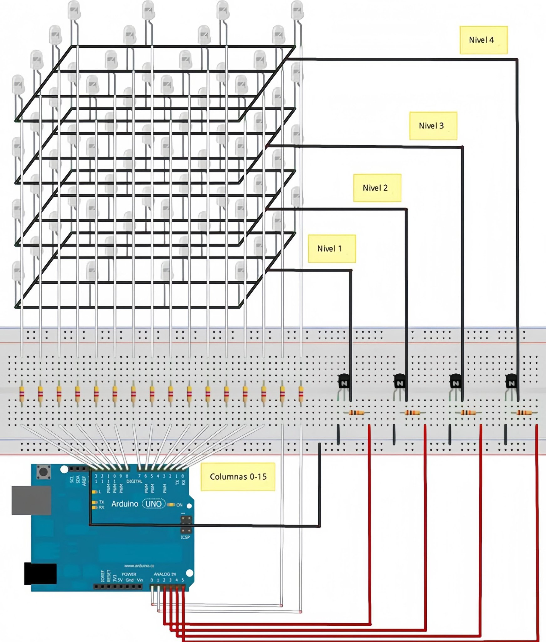
Nice circuit — that’s a 4×4×4 LED cube (4 levels × 16 columns). Below I give a complete Arduino UNO sketch you can upload, plus wiring notes and how to adapt pin mapping if your physical wiring is different.
Important wiring notes before the code
- The sketch assumes columns are connected individually to Arduino pins (through current-limiting resistors). Each column controls 4 LEDs (one per level).
- Each level (layer) is switched by an NPN transistor (or MOSFET) to sink the cathodes of that whole level. That means: to light a LED, set the corresponding column pin HIGH and turn ON (LOW for NPN base via resistor) the transistor for that layer to sink current — OR invert that logic if you wired it differently. I include a variable to change active logic if needed.
- Use current-limiting resistors on columns (typically 220–470 Ω) — one resistor per column is common.
- Avoid using Arduino pins 0 and 1 for normal IO if you need serial debugging (they are RX/TX). The mapping below does use 0 and 1 for layers as an example; change them if you want serial.
- If you want a more robust design use transistors/MOSFETs for layer switching and make sure the transistor base/gate resistor and common ground are correct.

Suggested pin mapping (change as needed)
I picked a mapping that uses 16 Arduino pins for columns and 4 for layers. If your wiring is different, edit the cols[] / layers[] arrays accordingly.
// Columns 0..15  -> Arduino pins
const uint8_t cols[16] = {
  2, 3, 4, 5,    // columns 0..3  (row 0 x=0..3)
  6, 7, 8, 9,    // columns 4..7  (row 1)
  10,11,12,13,   // columns 8..11 (row 2)
  A0,A1,A2,A3    // columns 12..15 (row 3)
};

// Layers z=0..3 -> Arduino pins (these control transistors)
const uint8_t layers[4] = { A4, A5, 0, 1 };
If you want to keep Serial (USB) for debugging, do not use pins 0 and 1. Replace them with other free pins or reassign some column pins to free up digital pins for layers.
The Sketch
This sketch provides:
setVoxel(x,y,z, on)andclearVoxelhelpers- A frame buffer
cube[z][y](4 planes × 4 rows, each byte uses 4 LSB bits for 4 columns) - Multiplexing by scanning layers quickly
- A few demo animations (fill, rotate, rain). You can add more.
Upload to Arduino UNO as-is (but update cols/layers to match your wiring).
/*
  4x4x4 LED cube Arduino sketch
  - Adjust pin mapping in cols[] and layers[] to match wiring
  - Columns should have current-limiting resistors (220-470 ohm)
  - Layers are switched by transistors (NPN to GND). If you use PNP/high-side, invert logic.
*/

const uint8_t cols[16] = {
  2, 3, 4, 5,
  6, 7, 8, 9,
  10,11,12,13,
  A0,A1,A2,A3
};

const uint8_t layers[4] = { A4, A5, 0, 1 };

// If your layer transistors turn ON with HIGH, set LAYER_ACTIVE = HIGH
// If transistors ON with LOW (common NPN sink), set LAYER_ACTIVE = LOW
const uint8_t LAYER_ACTIVE = LOW;
const uint8_t LAYER_INACTIVE = (LAYER_ACTIVE == LOW) ? HIGH : LOW;

// Frame buffer: cube[z][y] -> 4 planes z=0..3 each with 4 rows y=0..3. Bits 0..3 represent x=0..3
uint8_t cube[4][4];

const unsigned int layerRefreshMicros = 2000; // microseconds per layer (tweak for brightness/refresh)
unsigned long lastAnimMs = 0;
const unsigned long animInterval = 120; // ms between animation steps

// ------------------------------------------------------------------
// Helper functions
// ------------------------------------------------------------------
void setColumnOutput(int idx, bool high) {
  digitalWrite(cols[idx], high ? HIGH : LOW);
}

void activateLayer(int z) {
  // deactivate all layers
  for (int i = 0; i < 4; ++i) digitalWrite(layers[i], LAYER_INACTIVE);
  // activate requested
  digitalWrite(layers[z], LAYER_ACTIVE);
}

void deactivateAllLayers() {
  for (int i = 0; i < 4; ++i) digitalWrite(layers[i], LAYER_INACTIVE);
}

// set voxel (x in [0..3], y in [0..3], z in [0..3])
void setVoxel(uint8_t x, uint8_t y, uint8_t z, bool on) {
  if (x > 3 || y > 3 || z > 3) return;
  if (on) cube[z][y] |= (1 << x);
  else    cube[z][y] &= ~(1 << x);
}

void clearCube() {
  for (int z = 0; z < 4; ++z)
    for (int y = 0; y < 4; ++y)
      cube[z][y] = 0;
}

void fillCube() {
  for (int z = 0; z < 4; ++z)
    for (int y = 0; y < 4; ++y)
      cube[z][y] = 0x0F; // lower 4 bits on
}

// Send the buffer to hardware by multiplexing layers
// This function spends time refreshing layers; call it often in loop to maintain persistence
void refreshDisplay(unsigned long totalMillis) {
  unsigned long end = millis() + totalMillis;
  while (millis() < end) {
    for (int z = 0; z < 4; ++z) {
      // set columns pins according to cube[z]
      for (int col = 0; col < 16; ++col) {
        uint8_t x = col % 4;
        uint8_t y = col / 4;
        bool on = (cube[z][y] & (1 << x)) != 0;
        // column HIGH lights LED when its layer is active (assumes columns drive anodes HIGH)
        setColumnOutput(col, on);
      }
      // activate layer
      activateLayer(z);
      // hold for a short time for brightness
      delayMicroseconds(layerRefreshMicros);
      // quickly turn off before next layer to prevent ghosting while switching columns
      deactivateAllLayers();
    }
  }
}

// ------------------------------------------------------------------
// Some demo routines
// ------------------------------------------------------------------
void demoFillFlash() {
  fillCube();
  refreshDisplay(200);
  clearCube();
  refreshDisplay(200);
}

void demoRisingTowerStep() {
  // simple animation: raise a 4x4 plane upward
  static int level = 0;
  clearCube();
  for (int y = 0; y < 4; ++y) {
    for (int x = 0; x < 4; ++x) setVoxel(x, y, level, true);
  }
  level = (level + 1) & 3;
}

void demoRotateSquare() {
  // rotating pattern across layers
  static int step = 0;
  clearCube();
  if (step % 2 == 0) {
    // diagonal plane pattern
    for (int z = 0; z < 4; ++z) {
      for (int i = 0; i < 4; ++i) setVoxel((i + z) & 3, i, z, true);
    }
  } else {
    for (int z = 0; z < 4; ++z) {
      for (int i = 0; i < 4; ++i) setVoxel((i + 1 + z) & 3, i, z, true);
    }
  }
  step++;
}

// rain demo
void demoRainStep() {
  // shift all voxels down one z level and random top bits
  for (int z = 3; z > 0; --z) for (int y = 0; y < 4; ++y) cube[z][y] = cube[z-1][y];
  // new top layer random bits
  for (int y = 0; y < 4; ++y) cube[0][y] = (uint8_t)(random(0,16)); // random 4-bit pattern
}


// ------------------------------------------------------------------
// Setup and loop
// ------------------------------------------------------------------
void setupPins() {
  for (int i = 0; i < 16; ++i) pinMode(cols[i], OUTPUT);
  for (int i = 0; i < 4; ++i) pinMode(layers[i], OUTPUT);

  // ensure all columns LOW and layers inactive at start
  for (int i = 0; i < 16; ++i) digitalWrite(cols[i], LOW);
  deactivateAllLayers();
}

void setup() {
  // If you want Serial for debugging, avoid using pins 0 and 1 for layers!
  Serial.begin(115200);
  randomSeed(analogRead(A5));

  setupPins();
  clearCube();
  lastAnimMs = millis();
}

uint8_t demoMode = 0;

void loop() {
  // quick refresh while waiting for animation timing
  refreshDisplay(20); // refresh for 20ms continuously to keep persistence

  // animation timed separately
  if (millis() - lastAnimMs > animInterval) {
    lastAnimMs = millis();

    switch (demoMode) {
      case 0:
        demoFillFlash();
        demoMode = 1;
        break;
      case 1:
        demoRisingTowerStep();
        break;
      case 2:
        demoRotateSquare();
        break;
      case 3:
        demoRainStep();
        break;
    }

    // cycle demoMode every few seconds
    static int stepCount = 0;
    stepCount++;
    if (stepCount > 30) {
      stepCount = 0;
      demoMode = (demoMode + 1) % 4;
    }
  }
}
What to change if things don’t match your wiring
- Pin arrays: edit
cols[]andlayers[]to reflect your exact wiring. - Active layer polarity: set
LAYER_ACTIVEtoHIGHif a HIGH on the transistor gate/base activates the layer (e.g., P-channel/P-MOSFET high-side). For NPN sinking style (typical),LAYER_ACTIVE = LOWis correct if you use an NPN base resistor tied to the Arduino pin and the transistor is wired to pull the cathodes to ground. - Column drive logic: the code sets a column pin HIGH to turn a LED ON (when that layer is active). If your wiring is inverted (columns sink and layers source), invert
setColumnOutputcalls or wire differently. - Brightness / flicker: tweak
layerRefreshMicros. Smaller values = higher effective refresh speed and brighter display but more CPU time spent refreshing. For smoother animations, keep it low (1–3000 µs) and keeprefreshDisplay()running frequently. - Avoid pins 0/1 if you want Serial. Move layers to other pins and remap columns accordingly.